TBBZ High-Voltage Reactive Power Compensation | CANGO
CANGO supplies TBBZ high-voltage reactive power automatic compensation devices for HV power systems. Send rated data, drawings and quantity for quote.
Quantity :
add to cart
Contact Now
CANGO Product Detail
TBBZ High-Voltage Reactive Power Compensation | CANGO
Power Quality and DC Systems for B2B Electrical Projects
TBBZ High-Voltage Reactive Power Automatic Compensation Device is supplied for high-voltage reactive power compensation. CANGO reviews rated data, drawings, quantity, destination, and configuration notes before quotation.
TBBZ high-voltage reactive power automatic compensation device is designed for reactive power compensation in high-voltage distribution systems. It is commonly used for high-voltage reactive power compensation and industrial and utility distribution systems, with the final selection based on rated data, drawings, and site conditions.
electrical contractors, industrial plant engineers, EPC companies, maintenance teams, and project distributors can request configuration review for high voltage power compensation device. Please send system voltage, compensation or filtering capacity, control logic, monitoring requirements, cabinet quantity, and wiring diagram, quantity, destination, and any project standard requirements for quotation.
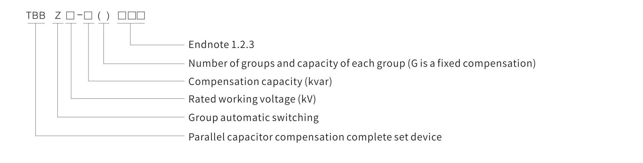
Model and Meaning
Key Features
01
Power Stability
TBBZ: The system can support compensation, filtering, control power, or monitoring needs according to project operating conditions. This point is especially relevant to high voltage power compensation device.
02
Monitoring Options
Controller, communication, metering, and alarm requirements can be reviewed before final configuration. For TBBZ, check this together with the selected project scheme.
03
Project-Matched Capacity
Capacity, current, voltage, and control logic should be selected according to the distribution system data. On TBBZ, confirm the application duty, site layout, and project standard before selection.
04
Reliable Operation
Protection, ventilation, wiring, and cabinet layout are checked together for stable long-term operation. Use the TBBZ drawings and rated data to confirm this point before quotation.
05
Technical Review
Drawings and system parameters help confirm whether the solution matches the actual electrical environment. For TBBZ, review this with high voltage power compensation device and the final installation plan.
Technical Specifications
Environmental Conditions for Use
Altitude:<= 1000 m
Ambient temperature: -25 degC to +55 degC
Relative humidity: <= 85%
Installation location: no explosive medium, corrosive gas, insulating gas, conductive medium, water vapor, or serious mold
Technical Specification
Review the TBBZ compensation protection, controller communication, reactor selection, rated voltage, rated frequency, capacity range, and group arrangement before quotation.
Item
Unit
Parameter
Single capacitor protection
Spray-type fuse protection; each group is equipped with a lightning arrester for operating overvoltage and lightning-strike protection.
Controller and communication
Large-screen LCD controller displays system voltage, current, and power factor in real time; RS232 / RS485 standard communication interface supports four remote-control functions.
Reactor configuration
Each group can be configured with a reactor to suppress closing inrush current or harmonic amplification.
Rated voltage
kV
6-10
Rated frequency
Hz
50
Rated capacity
kvar
100-10000
Number of groups
groups
1-5
Reactor parameter selection
%
0.1-1 for suppressing closing inrush current; 6 for suppressing harmonics above the 5th order; 12 for suppressing harmonics above the 3rd order.
Electrical Wiring Diagram
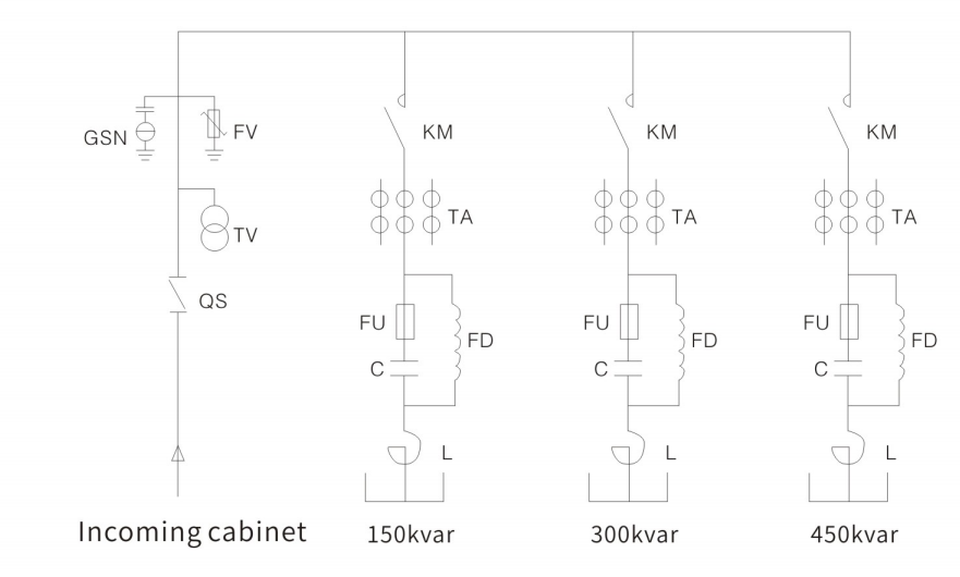
The wiring diagram shows the incoming cabinet and capacitor compensation group arrangement for 150 kvar, 300 kvar, and 450 kvar reference groups.
TBBZ electrical wiring diagram showing incoming cabinet and 150 kvar, 300 kvar, and 450 kvar capacitor compensation groups.
Installation Dimensions / Drawing
ForTBBZ, confirm the cabinet outline, ventilation space, wiring path, component arrangement, and control interface drawing. Use the confirmed technical table, project drawing, and site installation plan as the final dimensional reference before ordering or installation.
Applications
TBBZ is mainly selected for high-voltage reactive power compensation and industrial and utility distribution systems. The final application should match the confirmed high voltage power compensation device, rated data, and site installation conditions.
High-voltage reactive power compensation
Industrial and utility distribution systems
Projects requiring power factor and compensation control
Customization Options
Control Mode
Automatic control, manual control, communication, and monitoring options can be reviewed with the project wiring diagram. Apply this review to TBBZ and its high voltage power compensation device.
Capacity Selection
Compensation, filtering, DC output, or monitoring capacity should be matched with system voltage and load condition. Apply this review to TBBZ and its high voltage power compensation device.
Protection Devices
Fuse, breaker, surge protection, overvoltage, undervoltage, and alarm options can be selected by application. Apply this review to TBBZ and its high voltage power compensation device.
Cabinet Layout
Ventilation, wiring path, component arrangement, and maintenance access should be checked before final production. Apply this review to TBBZ and its high voltage power compensation device.
Monitoring and Stability
Monitoring Review
Controller, display, communication, alarms, and system monitoring options can be reviewed by project requirements. Apply this review to TBBZ and its high voltage power compensation device.
Stability Support
Compensation, filtering, DC control power, and protection functions should match the site operating condition. Apply this review to TBBZ and its high voltage power compensation device.
Efficiency and Reliability
Efficient Operation
Capacity, control logic, switching method, and load profile should be checked to support stable operation. Apply this review to TBBZ and its high voltage power compensation device.
Reliable Layout
Ventilation, wiring, component arrangement, and protection devices should be confirmed before final cabinet production. Apply this review to TBBZ and its high voltage power compensation device.
Ordering Instructions / Information Required for Quotation
Ordering Instructions / Information Required for Quotation
Please specify any special requirements for compensation capacity and grouping for the full range of product models.
Confirm whether a microcomputer monitoring device is required, and state whether the installation type is indoor or outdoor.
When a reactor is required, provide the harmonic situation, especially the order of the lowest harmonic.
TBBZ is used for High-voltage reactive power compensation, Industrial and utility distribution systems, Projects requiring power factor and compensation control. The final selection should match the project voltage, current, circuit arrangement, and installation conditions.
Which buyers commonly source TBBZ?
electrical contractors, industrial plant engineers, EPC companies, maintenance teams, and project distributors commonly use this product for project-based electrical distribution, installation, replacement, or system expansion work.
Which rated voltage or current should be confirmed for TBBZ?
Confirm the rated voltage, rated current, short-circuit level, frequency, protection level, and configuration shown in the technical specifications before quotation.
CanTBBZ be configured for a specific project?
Yes.CANGO can review project-specific configurations according to drawings, rated data, protection requirements, component requirements, and site conditions before quotation.
Which standards should be confirmed?
Applicable standards depend on the project and destination market. State IEC, local utility, component, testing, or documentation requirements in the inquiry.
What installation information is required?
TBBZ should be matched with the final project drawing and outline data before installation. Send the cabinet scheme or layout requirement for review.
What information is needed for quotation?
For quotation, send system voltage and application, rated current, capacity, or output requirement, wiring diagram or cabinet layout, monitoring, protection, communication, and component requirements, quantity, project country, delivery requirement, and any special component or environmental requirements.
How is delivery time confirmed for TBBZ?
Delivery time depends on the confirmed configuration, quantity, component selection, documentation requirement, and production schedule. Share the project deadline during inquiry.
Send project data for TBBZ. The fields below are the recommended information for quotation and technical review.
Use the buttons below to send the project request by email or open the contact page. If you have drawings, attach the file in the email or share a file link in the message.
This is project-based power distribution equipment. Share the single-line diagram, rated data, cabinet arrangement, quantity, and destination, and CANGO will review the configuration before quotation.
============================================================ NO. 11 Status: DRAFT READY FOR CMS REVIEW Model No.: SRM-12 Category: Medium-Voltage Switchgear Proposed URL: https://www.cncango.com/products/srm-12-gas-insulated-ring-main-unit.html Selected CMS Keywords: 12kv rmu supplier | gas insulated switchgear manufacturer | compact medium voltage rmu factory | expandable rmu exporter SEO Title: SRM-12 12kV Gas-Insulated RMU | CANGO Meta Description: CANGO supplies SRM-12 12kV Gas-Insulated RMU for urban and rural distribution systems. Send rated data, drawings, quantity, and destination for quotation. H1: SRM-12 12kV Gas-Insulated RMU | CANGO Installation Dimension Image Upload Reference: - Local source: D:我的文档Documents项目1power-transmission-distribution-structure-drawing-imagessrm-12-gas-insulated-ring-main-unit-cabinet-arrangement-drawing.png Source status: Available Recommended CMS file name: srm-12-gas-insulated-ring-main-unit-cabinet-arrangement-drawing.png Delivery URL: /uploads/power-transmission-distribution/srm-12-gas-insulated-ring-main-unit-cabinet-arrangement-drawing.png Recommended ALT text: SRM-12 gas-insulated ring main unit cabinet arrangement drawing Model and Meaning Diagram Image Upload Reference: - No standalone model-and-meaning diagram is present in the source technical document. Keep this section hidden unless verified model-meaning content is available. Technical Parameter Image Upload Reference: - No extra technical-parameter image is required below the searchable table. Template note: use the CMS product title field as the page H1. The HTML source below starts under that H1 to avoid duplicate H1 tags. HTML Source:
CANGO Product Detail
SRM-12 12kV Gas-Insulated RMU | CANGO
Medium-Voltage Switchgear for B2B Electrical Projects
SRM-12 12kV Gas-Insulated RMU is supplied for urban and rural distribution systems. CANGO reviews rated data, drawings, quantity, destination, and configuration notes before quotation.
SRM-12 is a 12kV gas-insulated RMU for 6kV and 10kV medium-voltage distribution systems. It is commonly used for urban and rural distribution systems and compact substations, with the final selection based on rated data, drawings, and site conditions.
EPC companies, electrical contractors, utility project teams, panel builders, and industrial buyers can request configuration review for sealed modular RMU configuration. Please send single-line diagram, rated voltage, rated current, short-circuit level, protection scheme, busbar arrangement, and cabinet layout, quantity, destination, and any project standard requirements for quotation.
Key Features
01
Safe Switching
SRM-12: The cabinet scheme can be reviewed for rated voltage, rated current, short-circuit level, interlocking, and protection requirements. This point is especially relevant to sealed modular RMU configuration.
02
Flexible Configuration
Incoming, outgoing, metering, busbar, and protection arrangements can be matched to the project single-line diagram. For SRM-12, check this together with the selected project scheme.
03
Utility Project Fit
The equipment is suitable for distribution rooms, substations, cable networks, and infrastructure power systems. On SRM-12, confirm the application duty, site layout, and project standard before selection.
04
Drawing-Based Selection
Cabinet width, depth, cable trench, busbar interface, and foundation details should be confirmed from project drawings. Use the SRM-12 drawings and rated data to confirm this point before quotation.
05
Maintenance Planning
Access, isolation, grounding, and operation sequence requirements can be reviewed before quotation. For SRM-12, review this with sealed modular RMU configuration and the final installation plan.
Technical Specifications
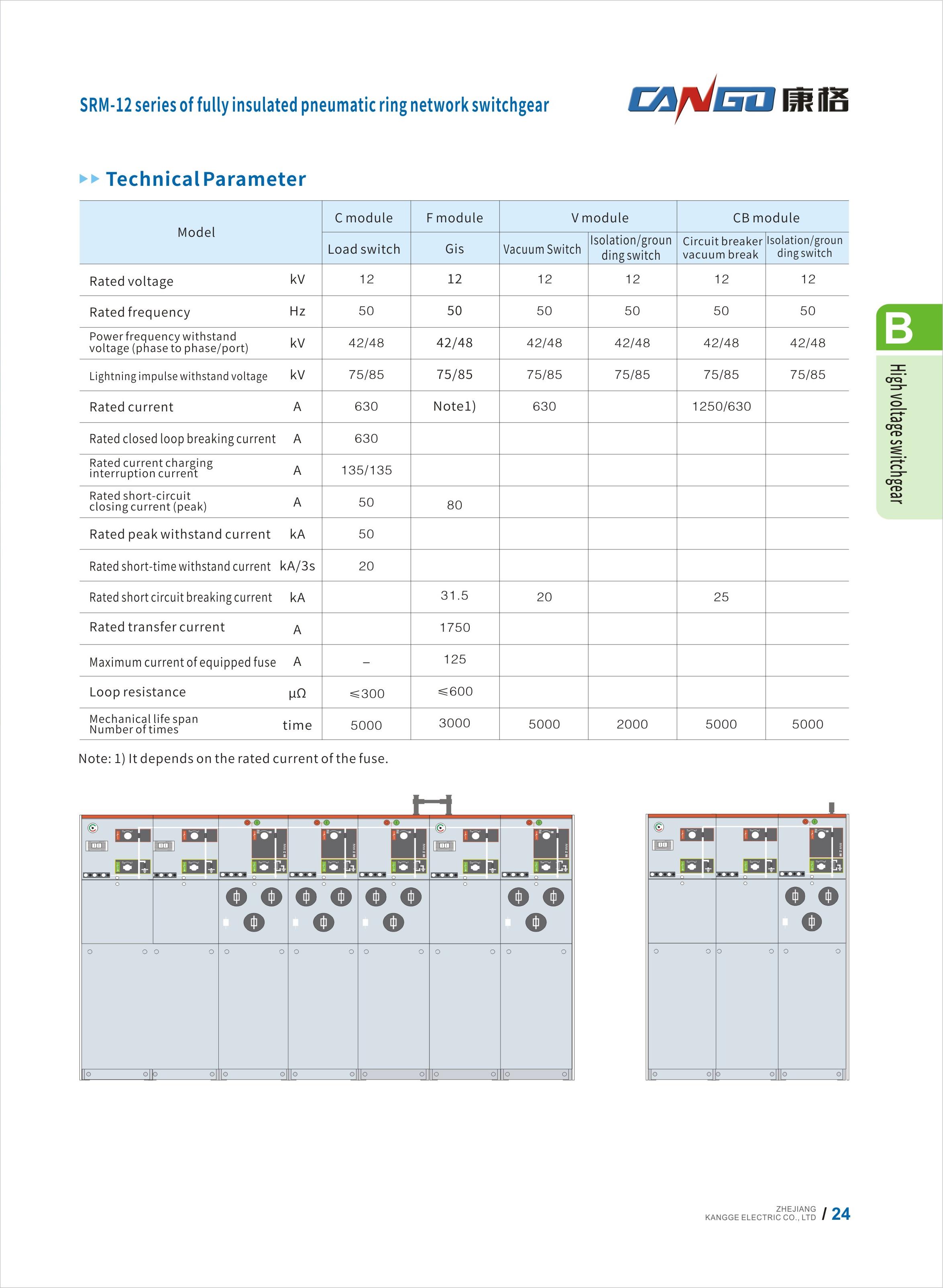
SRM-12 Technical Parameter Table
Review the SRM-12 module arrangement, rated data, and selected configuration before quotation.
Item
Unit
C module
F module
V module
CB module
Load switch
GIS
Vacuum switch
Isolation / grounding switch
Circuit breaker vacuum break
Isolation / grounding switch
Rated voltage
kV
12
12
12
12
12
12
Rated frequency
Hz
50
50
50
50
50
50
Power-frequency withstand voltage, phase to phase / port
kV
42 / 48
42 / 48
42 / 48
42 / 48
42 / 48
42 / 48
Lightning impulse withstand voltage
kV
75 / 85
75 / 85
75 / 85
75 / 85
75 / 85
75 / 85
Rated current
A
630
Note 1
630
1250 / 630
Rated closed-loop breaking current
A
630
Rated current charging interruption current
A
135 / 135
Rated short-circuit closing current, peak
A
50
80
Rated peak withstand current
kA
50
Rated short-time withstand current
kA / 3 s
20
Rated short-circuit breaking current
kA
31.5
20
25
Rated transfer current
A
1750
Maximum current of equipped fuse
A
-
125
Loop resistance
micro-ohm
<= 300
<= 600
Mechanical life span, number of times
time
5000
3000
5000
2000
5000
5000
Note 1: It depends on the rated current of the fuse.
Source Technical Parameter Reference
SRM-12 source technical parameter table for checking capacity-specific values, loss data, dimensions, and project selection.
Installation Dimensions / Drawing
SRM-12 cabinet arrangement drawing showing module front views for ring main unit configuration review.
Applications
SRM-12 is mainly selected for urban and rural distribution systems and compact substations. The final application should match the confirmed sealed modular RMU configuration, rated data, and site installation conditions.
Urban and rural distribution systems
Compact substations
Cable network and project distribution rooms
Customization Options
Protection Options
Relay protection, metering, interlocking, grounding, and auxiliary circuit requirements can be reviewed by single-line diagram. Apply this review to SRM-12 and its sealed modular RMU configuration.
Busbar Configuration
Single busbar, sectional busbar, incoming, outgoing, metering, and bus-tie arrangements should be confirmed before quotation. Apply this review to SRM-12 and its sealed modular RMU configuration.
Cable Interface
Cable entry, cable trench, termination space, and grounding arrangement can be checked with the cabinet layout drawing. Apply this review to SRM-12 and its sealed modular RMU configuration.
Operation Scheme
Fixed, removable, ring-main, GIS, or modular arrangements are selected according to the project network design. Apply this review to SRM-12 and its sealed modular RMU configuration.
Single Line Diagram
Drawing Input
Provide the project single-line diagram so incoming, outgoing, metering, bus-tie, and protection functions can be reviewed. Apply this review to SRM-12 and its sealed modular RMU configuration.
Scheme Review
Rated voltage, rated current, short-circuit level, operating sequence, and cabinet quantity should match the final network design. Apply this review to SRM-12 and its sealed modular RMU configuration.
Protection Options
Relay and Metering
Protection relay, metering, auxiliary circuit, and communication requirements can be selected according to the project specification. Apply this review to SRM-12 and its sealed modular RMU configuration.
Safety Interlocking
Interlocking, grounding, isolation, and operation sequence requirements should be confirmed before final cabinet design. Apply this review to SRM-12 and its sealed modular RMU configuration.
Busbar Configuration
Busbar Arrangement
Single busbar, sectional busbar, bus coupler, and incoming / outgoing cabinet order can be checked from the layout. Apply this review to SRM-12 and its sealed modular RMU configuration.
Interface Review
Busbar current, cable trench, cabinet depth, and connection interface should be confirmed before production. Apply this review to SRM-12 and its sealed modular RMU configuration.
Ordering Instructions / Information Required for Quotation
ForSRM-12, send single-line diagram, rated voltage, rated current, short-circuit level, protection scheme, busbar arrangement, and cabinet layout, quantity, destination, and the expected delivery schedule. The engineering review will be based on the selected sealed modular RMU configuration and project drawing.
ORDERING INSTRUCTIONS
State the required SRM-12 configuration, quantity, project destination, and intended application.
Provide single-line diagram, rated voltage, rated current, short-circuit level, cabinet quantity, component configuration, and protection requirements for technical review.
Confirm confirm the final cabinet outline, foundation channel, cable trench, busbar interface, and cabinet arrangement drawing before final production or installation planning.
List any special environmental, wiring, communication, metering, protection, or component requirements in the inquiry.
SRM-12 is used for Urban and rural distribution systems, Compact substations, Cable network and project distribution rooms. The final selection should match the project voltage, current, circuit arrangement, and installation conditions.
Which buyers commonly source SRM-12?
EPC companies, electrical contractors, utility project teams, panel builders, and industrial buyers commonly use this product for project-based electrical distribution, installation, replacement, or system expansion work.
Which rated voltage or current should be confirmed for SRM-12?
Confirm the rated voltage, rated current, short-circuit level, frequency, protection level, and configuration shown in the technical specifications before quotation.
CanSRM-12 be configured for a specific project?
Yes.CANGO can review project-specific configurations according to drawings, rated data, protection requirements, component requirements, and site conditions before quotation.
Which standards should be confirmed?
Applicable standards depend on the project and destination market. State IEC, local utility, component, testing, or documentation requirements in the inquiry.
What installation information is required?
SRM-12 should be matched with the final project drawing and outline data before installation. Send the cabinet scheme or layout requirement for review.
What information is needed for quotation?
For quotation, send single-line diagram, rated voltage and rated current, short-circuit level, number of incoming and outgoing feeders, quantity, project country, delivery requirement, and any special component or environmental requirements.
How is delivery time confirmed for SRM-12?
Delivery time depends on the confirmed configuration, quantity, component selection, documentation requirement, and production schedule. Share the project deadline during inquiry.
Send project data for SRM-12. The fields below are the recommended information for quotation and technical review.
Use the buttons below to send the project request by email or open the contact page. If you have drawings, attach the file in the email or share a file link in the message.
This is project-based power distribution equipment. Share the single-line diagram, rated data, cabinet arrangement, quantity, and destination, and CANGO will review the configuration before quotation.